
NEMA Wiring Diagram Manual for Electrical Specialists
About seventy percent of the electrical breakdowns across facilities are due to poor wiring techniques. These figures emphasizes the necessity of following established guidelines, underscoring NEMA wiring schematics’ significance for electrical experts. Via these diagrams, wiring configurations that satisfy both functional productivity and optimal protection norms are delineated.
The aim of this guide is to equip electrical professionals with comprehensive insights into NEMA standards. Stressing the significance of correct electrical installations is vital. By mastering these guidelines, technicians can significantly reduce the risk of hazards and confirm they meet safety measures endorsed by Installation Parts Supply. Knowledge in l14-30 plug wiring diagram is crucial whether creating modern setups or servicing current ones, as it improves the capacity to provide safe and consistent electrical answers.
Key Highlights
- NEMA wiring diagrams are crucial for maintaining electrical safety and adherence.
- Adequate wiring methods can reduce electrical malfunctions substantially.
- Comprehending NEMA criteria boosts the efficiency of electrical installations.
- Installation Parts Supply promotes adherence to safety standards in electrical tasks.
- NEMA diagrams accommodate a broad spectrum of uses across different industries.
Grasping NEMA Criteria and Their Importance
NEMA norms are pivotal in the electrical sector, guiding safety and performance precisely. Formulated by the National Electrical Manufacturers Association, they define pivotal benchmarks for designing, testing, and labeling electrical equipment. It ensures uniformity and dependability across all electrical installations, which is of great value.
What Are NEMA Norms?
NEMA designations span from classes 1 to 13. Every level specifies the parameters suitable for electrical appliances to operate effectively. For instance, NEMA 1 offers basic indoor security but is missing dust shielding. On the other hand, NEMA 4 ensures devices is waterproof, a necessity for surviving significant water exposure. Grasping these designations is crucial in selecting appropriate appliances.
Why NEMA Norms Matter for Electrical Security
The function of NEMA norms in maintaining electrical protection is significant. They contribute greatly in reducing electric shock, equipment failures, and fire dangers. Accurate adherence to NEMA standards empowers devices to operate reliably under certain ambient conditions. For outdoor application, NEMA 3 ratings deliver protection against the elements, safeguarding the equipment from adverse conditions like precipitation and snowfall. In zones susceptible to explosions, ratings like NEMA 7, 8, and 9 are critical for ensuring security.
Implementations of NEMA Norms in Wiring Diagrams
The use of NEMA norms in wiring diagrams is crucial for protected, optimal electrical systems. These diagrams employ consistent symbols and formats originating from NEMA ratings, streamlining the interpretation of complex electrical setups. Such standardization is beneficial. It promotes clarity, uniformity, and diminishes misinterpretations, thus improving electrical protection across home and commercial landscapes.
NEMA Wiring Diagram Basics
NEMA wiring schematics are vital for electrical experts, ensuring complex junctions unambiguous. They outline the connections and elements in different setups. By understanding the components, types, and notations of NEMA diagrams, electricians can improve their work in deployments and servicing.
Constituents of NEMA Wiring Drawings
NEMA drawings include key elements for particular electrical installations. You’ll find wiring endpoints, connectors, and additional hardware for secure connections. Each piece ensures power is spread efficiently, in accordance with security standards.
Categories of NEMA Wiring Diagrams
NEMA uses different diagrams, like connection diagrams and electrical arrangements. These schematics outline equipment relationships, while arrangements display energy distribution. Selecting the appropriate drawing aids in problem solving and deployment.
Typical Icons Employed in NEMA Wiring Schematics
Icons in wiring drawings are crucial for unambiguous clarity. They illustrate switches, networks, and interfaces. Understanding these symbols assists teams interpret drawings properly. Such practice ensures setups comply with NEMA criteria.
NEMA Wiring Schematic Attributes
For electrical experts, comprehending the fundamental aspects of detailed electrical wiring schematics is crucial. These schematics bring both transparency and completeness, aligning configurations with NEMA criteria. They require precise labeling and sizing to minimize installation errors. This fosters a safer and more efficient workplace.
Key Features of Correct Electrical Wiring Drawings
Accurate electrical wiring diagrams are indispensable in electrical initiatives. They incorporate important features such as:
- Lucidity: Schematics must be unambiguous, lowering errors in understanding.
- Completeness: They should incorporate all key elements, linkages, and electrical classifications.
- Adherence to Standards: Complying with NEMA standards is imperative for securing security and performance.
- Thorough Annotation: Unambiguous annotations on each part are crucial for grasping and error prevention.
- Correct Scaling: The dimensions should mirror the real setup to depict the arrangement accurately.
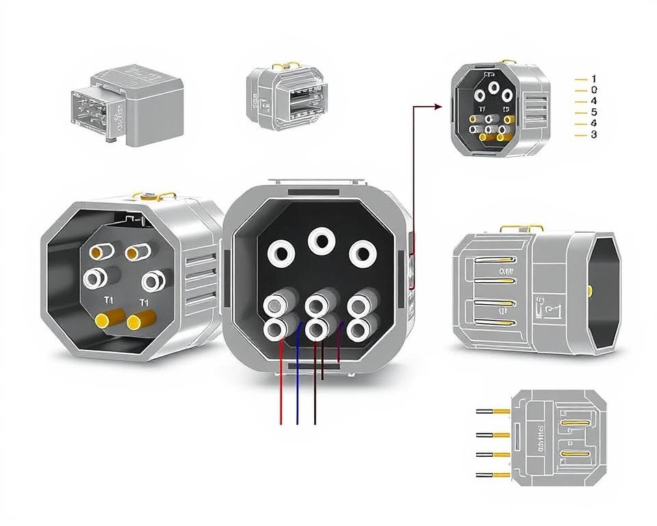
Comprehending NEMA Coupler Configuration
The insight into NEMA connector configuration is vital for making accurate linkages in electrical systems. Knowledge about distinct pin arrangements upholds security and device functionality. There is a diversity of NEMA couplers, designed for specific voltage levels and flows, covering:
| NEMA Connector Type | Current Rating | Power Rating |
|---|---|---|
| L5-15 | 15A | 125V |
| L5-20 | 20A | 125V |
| L14-20 | 20A | 125/250V |
| L1430C | 30A | 125/250V |
| L620C | 20A | 250V |
| L1430C | 30A | 125/250V |
| L630R | 30A | 250V |
Comprehending NEMA coupler configurations is crucial for secure junctions, enhancing efficiency. It’s imperative to match interfaces with devices accurately using locking or linear blade variants, to avoid safety risks.
NEMA Device Wiring
NEMA device wiring covers various arrangements for safe electrical appliance connections. These standards ensure that devices operate in unison securely, lowering danger. Grasping the diverse NEMA equipment and their wiring is essential for technicians.
Different Kinds of NEMA Devices
NEMA categorizes units by type based on power levels and amperage needs. Key configurations are:
- 2-Pole 2-Wire
- 2-Pole 3-Wire Grounding
- 3-Pole 3-Wire
- 3-Pole 4-Wire Grounding
- 4-Pole, 4-Wire
- 4-Pole 5-Wire Grounding
These arrangements find use in homes and manufacturing plants, handling 125V, 208V, and 480V.
NEMA Plug Wiring Demystified
NEMA plug wiring differs to suit various energy requirements, with rotary-lock types ensuring reliable interfaces in vibrating conditions. For instance, the L5-15 plug is rated for 15 amps, frequently used in commercial locations, whereas the L14-20 is intended for 20 amperes at 125/250 voltage.
The NEMA naming scheme assists in selecting the right plugs, highlighting features like electrical polarity and grounding. This meticulousness ensures that appliances operate securely.
NEMA Outlet Wiring Instructions
Accurate wiring of NEMA outlets conforms to electrical regulations and safety norms. For instance, L530R receptacles are configured for 30 A at 125 volts, with L630R models for 250 voltage. Correct grounding is crucial to avoid electrical mishaps.
Selecting accredited NEMA plugs and sockets ensures protected, code-compliant installations. It’s imperative to consult formal standards when setting up.
NEMA Motor Wiring and Implementations
NEMA motor wiring is essential in electrical systems, notably for industrial use. Grasping how NEMA motor setup works secures that engines are set up for best operation. Such devices, like one-phase and three-phase types, need proper wiring to operate securely and efficiently.
Summary of NEMA Motor Wiring
Comprehending NEMA motor wiring demands familiarity of linkages and arrangements. Most three-phase motors are compatible with dual-voltage, meaning they can work on both low (208-230V) and high voltage (460V). Wiring at high voltage results in lower current draw than at low voltage. High voltage advantages comprise smaller wires for the input, a major benefit for motors exceeding 10 HP.
While both NEMA and IEC units are used in the market, NEMA versions are typically bigger and priceier than IEC ones for less than 100 HP uses. NEMA trips vary from size 00 to 9, suitable for multiple applications. A standard feature in NEMA controllers is a Fault Class of 20, designed to trigger when a motor’s amperage exceeds 6x the Full Load Amperage in 10 s.
Choosing the Appropriate NEMA Motor Arrangement
Selecting the right NEMA motor setup impacts overall efficiency and protection. A common three-wire control circuit employs three wires for a power control pushbutton interface, allowing simple motor operation. Frequent three-phase setups include the 12 Lead Dual Voltage and 6 Lead, facilitating Wye and Delta configurations.
IEC motor starters commonly feature phase failure detection, boosting safety. They also feature modifiable Fault Classes for tailored protection in low power operations. Additionally, many units have thermal protection, vital for Single Phase and Dual Voltage systems.
| Arrangement | Voltage Level | Amperage | Usual Function |
|---|---|---|---|
| 12 Lead Dual Voltage | Dual Voltage (208-230V / 460V) | Varies by motor size | Applications with Wye Start and Delta Run |
| 6 Lead | Single/Dual Voltage | 32 amps maximum | Both Wye and Delta arrangements |
| Single Phase | One Voltage | Varies (1-5 amps adjustment) | Two Speed, Two Winding applications |
| Delta Connection | High-Power Voltage | Depending on setup | Current Transformers, multiple configurations |
Final Thoughts
Comprehending NEMA wiring drawings and standards is vital for electrical specialists seeking to boost their capabilities and comply with electrical safety norms. These standards not only ensure secure and high-performing electrical configurations but also prevent hazards linked to improper wiring. As discussed, complying with NEMA criteria yields the enhanced performance of diverse NEMA units and configurations.
For technicians, the selection of superior materials can greatly affect the success of their work. Installation Parts Supply offers a extensive range of wiring products in accordance with NEMA norms. This enables experts to get critical elements for complying with these key regulations. Premium materials and profound understanding of NEMA wiring diagrams substantially improve project protection and efficiency.
During electrical setups, always put safety and accuracy first. Gaining expertise in NEMA criteria delivers the understanding required to executing best practices accurately. This secures that every electrical connection made meets premium norms.
Common Questions
Identify NEMA wiring drawings?
NEMA wiring schematics illustrate the arrangements and connections of NEMA-standard electrical appliances. They follow safety and functional standards established by the National Electrical Manufacturers Association.
What makes NEMA standards important for electrical safety?
NEMA standards are essential to defining safety and functional criteria for electrical devices. These guidelines assist electrical specialists minimize electric shock, device malfunctions, and fire hazards.
Identify the key parts are crucial in a NEMA wiring diagram?
Fundamental parts in a NEMA wiring schematic consist of circuit setups and junction blueprints. These drawings also feature comprehensive markings and show the electrical system’s different parts accurately for installations.
What types of NEMA wiring schematics are available?
Diverse NEMA wiring drawings address diverse requirements, including circuitry for power distribution and connector schematics. Every diagram serves a distinct role in electrical installations.
Which are the typical symbols employed in NEMA wiring diagrams?
Standard symbols in these drawings symbolize switches, interruptors, outlets, and more. Use of these symbols promotes effective interaction and correct interpretation of wiring diagrams.
Identify the essential attributes of precise electrical wiring diagrams?
Correctness in electrical wiring schematics is marked by their clarity, comprehensiveness, and detailed labeling. They need to meet NEMA norms to avoid mistakes in setup.
What is a NEMA connector layout?
A NEMA connector configuration outlines electrical junctions at a connector, displaying distinct pin functions. This secures safe and efficient linkages in electrical setups.
Which are the various kinds of NEMA units?
NEMA appliances comprise various electrical sockets and connectors, like adapters and receptacles. They are crafted for diverse current and voltage levels criteria to fulfill unique usage needs.
Describe how NEMA plug wiring arranged?
NEMA plug wiring is determined by specific amperage and power needs, adhering to safety guidelines and code compliance for multiple electrical setups.
Which standards are there for NEMA outlet wiring?
Standards for installing NEMA outlets emphasize following electrical codes, securing accurate electrical polarity, and choosing appropriate wire sizes. This sustains both protection and functionality in electrical installations.
What is the method to wire a NEMA motor efficiently?
To set up a NEMA motor, one must understand its defined single-phase or tri-phase configuration. Opting for the appropriate wiring approach is essential, plus practicing electrical security for maximum motor performance.
What should I consider when choosing a NEMA motor arrangement?
Selecting a NEMA motor configuration necessitates an analysis of the project’s voltage and current demands and performance traits. It’s also vital to confirm compatibility with current systems for reliable performance and security.